- A central processing unit (CPU) is the hardware within a computer that carries out the instruction of a computer program by performing the basic arithmetical, logical, control and input/output operations of the system. The term has been in use in the computer industry at least since the early 1960. The form, design,and implementation of CPU have changed over the course of their history, but their fundamental operation remains much the same.

- Two typical components of a CPU are the arithmetic logic unit (ALU), which performs arithmetic and logical operations, and the control unit (CU), which extracts instructions from memory and decodes and executes them, calling on the ALU when necessary.
- Measuring Execution Time
CPU Time = Instruction x Clock cycles x Seconds
Program Instruction Clock cycles
Instruction execution
 |
| CPU overview |
- All instruction start by using the program counter to supply the instruction address to the instruction memory.
- After the instruction is fetched, the register operands used by an instruction are specified by fields of that instruction.
- Once the register operands have been fetched, they can be operated on to compute a memory address (for a load or store), to compute an arithmetic result (for an integer arithmetic-logical instruction), or a compare (for a branch).
- If the instruction is an arithmetic-logical instruction, the result from the ALU must be written to a register.
- If the operation is a load or store, the ALU result is used as an address to either store a value from the registers or load a value from memory into the registers.
- The result from the ALU or memory is written back into register file.
- Branches require the use of the ALU output to determine the next instruction address, which comes either from the ALU (where the PC and branch offset are summed) or from an adder that increments the current PC by 4.
- The thick lines interconnecting the functional units represent buses, which consists of multiple signals
Logic Design Conventions
Combinational elements
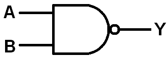
- AND-gate
- Multiplexer

- Adder

- Pipelining analogy
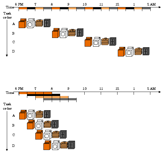
Four loads:
- Speedup = 8/3.5 = 2.3
- Non-stop:
- Speedup = 2n/0.5n + 1.5 ≈ 4 = number of stages
- MIPS Pipeline
Five stages, one step per stage:
- IF : Instruction fetch from memory
- ID : Instruction decode & register read
- EX : Execute operation or calculate address
- MEM : Access memory operand
- WB : Write result back to register
- Pipeline Speedup
- If all stages are balanced
~i.e., all take the same time

2. If not balanced, speedup is less
3.Speedup due to increased throughput
~Latency (time for each instruction) does not decrease
4. Ideally 5 stage pipeline should offer nearly fivefold improvement over the 800 ps nonpipelined time.
- en.wikipedia.org/wiki/AND_gate
- www.cs.ccsu.edu/~markov/ccsu_courses/502-4.pdf
- http://upload.wikimedia.org/wikipedia/commons/thumb/2/21/Single_bus_organization.jpg/220px-Single_bus_organization.jpg
No comments:
Post a Comment