
 Input device is piece of computer hardware equipment that used to provide data and control signals to an information processing system such as a computer or other information appliance.
 An output device is any piece of computer hardware equipment used to communicate the results of data processing carried out by an information processing system (such as a computer) which converts the electronically generated information into human-readable form.
◦Behaviour: input, output, storage
◦Partner: human or machine
◦Data rate: bytes/sec, transfers/sec
I/O System may refer to:- DOS BIOS (Basic Input/Output System), a low-level component in DOS operating systems, including PC DOS and DR-DOS
- I/O System (86-DOS), the DOS-BIOS specifically in 86-DOS
- I/O System (MS-DOS), the DOS-BIOS specifically in MS-DOS
 I/O system characteristics
 Dependability is important
◦Particularly for storage devices
Performance measures◦Latency (response time)
◦Throughput (bandwidth)
◦Desktops & embedded systems
Mainly interested in response time & diversity of devices◦Servers
Mainly interested in throughput & expandability of devices| I/O BUS CONNECTIONS |
Function of I/O modules:
1) Control and Timing.
 |
| I/O MODULE STRUCTURE |
 CPU asks I/O module to check the status of attached device. I/O module tells the status.CPU requests for data transfer to I/O module if device is ready.I/O module gathers the data and transfers to the CPU.
2) CPU Communicating.
Command Decoding : Like read/write seek etc.Data - Exchange between CPU and Module.Status reporting - to CPU, since peripherals are slow.Address recognition for the devices connected to it.
3) Device Communication.
This may involves command, status information and data transfer.
4) Data Buffering.
Essential function to overcome speed mismatch.
5) Error Detection.
Like paper jam, bad data etc.
Interconnecting components:
Need interconnections between
◦CPU, memory, I/O controllers
Bus: shared communication channel
◦Parallel set of wires for data and synchronization of data transfer
◦Can become a bottleneck
Performance limited by physical factors
◦Wire length, number of connections
More recent alternative: high-speed serial connections with switches
◦Like networks
Bus signals and synchronization
Data lines
◦Carry address and data
◦Multiplexed or separate
Control lines
◦Indicate data type, synchronize transactions
Synchronous
◦Uses a bus clock & a fixed protocol for communicating. E.g. perform a read from memory: 1st clock cycle need a protocol to transmit the address and read command using control lines. 5th clock cycle, the memory need to respond eith the data word.
◦Adv= fast. Disadv= clock skew and synchronization problem.
Asynchronous
◦Uses request/acknowledge control lines for handshaking to accommodate a wide variety of devices of differing speed
◦Solve clock skew and synchronization prob.

Techniques of I/O
i. Programmed I/O : The CPU issues a command then waits for I/O operations to be complete. If the CPU is faster than the I/O module then this method is wasteful of CPU time.
ii. Interrupt Driven I/O : The CPU issues commands then proceeds with its normal work until interrupted by I/O device on completion of its work.
iii. DMA : In this CPU and I/O Module exchange data without involvement of CPU.
iv. Memory mapped I/O : there is a single address space for memory locations and I/O devices. CPU treats the status and data registers of I/O modules as memory locations and uses the same machine instructions to access both memory and I/O devices.
v .Isolated I/O : a dedicated instruction that is used to give a command to an I/O device. It specifies both the device number and the command.
Programmed I/O
The code in the OS for Programmed I/O be more like:
keyboard_wait: ; for get_ch
test Keyboard_Status, 80000000h
jz keyboard_wait
mov eax, Keyboard_Data
and
display_wait: ; for put_ch
test Display_Status, 80000000h
jz display_wait
mov Display_Data, eax
This scheme is known as BUSY WAITING, or SPIN WAITING. The little loop is called a SPIN WAIT LOOP.
 Problems with programmed I/O
*much time is wasted spin waiting.
if it takes 100 instructions to program this, and each instruction takes 20ns to execute, then it takes
100 * 20nsec = 2000nsec = 2 usec to execute
if a device takes 2msec (=2000usec) to deal with one character, then the percent of time spent waiting
time waiting / total time = 2000us / 2000us +2us =99.9%
We'd like a solution that spent less time "doing nothing"
Interrupts
 |
| interrupt processing |
When a device is ready or error occurs
◦Controller interrupts CPU
Interrupt is like an exception
◦But not synchronized to instruction execution
◦Can invoke handler between instructions
◦Cause information often identifies the interrupting device
Priority interrupts
◦Devices needing more urgent attention get higher priority
◦Can interrupt handler for a lower priority interrupt
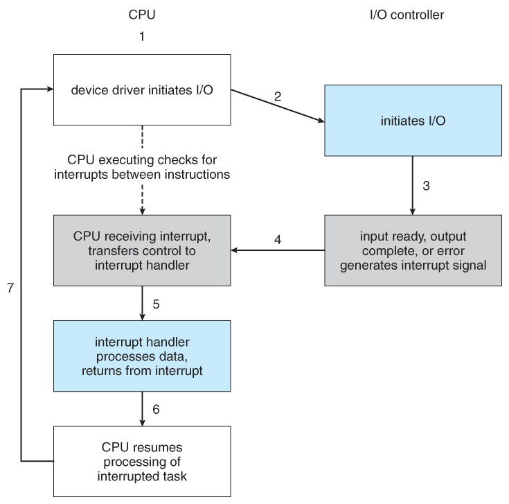 |
| INTERRUPT DRIVEN CYCLE |
| INTERRUPT DRIVEN DATA STRUCTURE |
Direct Memory Access
Special Purpose Processor: DMA controller◦Free CPU from pure data transfer tasks
◦DMA access: Pointer to source, destination and size of data issued to start transfer
◦Processor writes the data DMA access data and continuous working
◦Handshake protocol
DMA request and DMA acknowledgeDMA controllers are standard components in PCsthere are two type of I/O transfer mode:Serial◦In band signaling
◦Bit oriented
◦Bit/byte word translation
Parallel◦Byte word oriented
◦Out of band signaling
◦IDE, SCSI
I/O vs. CPU PERFOMANCEAmdahl’s Law◦Don’t neglect I/O performance as parallelism increases compute performance
Example◦Benchmark takes 90s CPU time, 10s I/O time
◦Double the number of CPUs/2 years
I/O unchangedI/O system designSatisfying latency requirements◦For time-critical operations
◦If system is unloaded
Add up latency of componentsMaximizing throughput◦Find “weakest link” (lowest-bandwidth component)
◦Configure to operate at its maximum bandwidth
◦Balance remaining components in the system
If system is loaded, simple analysis is insufficient◦Need to use queuing models or simulation
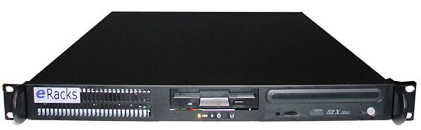 |
| RACK-MOUNTED SERVER |
Server computersApplications are increasingly run on servers◦Web search, office apps, virtual worlds, …
Requires large data center servers◦Multiple processors, networks connections, massive storage
◦Space and power constraints
Server equipment built for 19” racks◦Multiples of 1.75” (1U) high
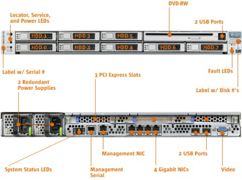 |
| SUN FIRE x4150 1U SERVER |
sources :
http://en.wikipedia.org/wiki/Input_device
http://en.wikipedia.org/wiki/Output_device
http://en.wikipedia.org/wiki/I/O_System